The Ultimate Guide to Orifice Plates: Engineering, Sizing, and Compliance
In the world of industrial flow measurement, the Orifice Plate remains the most widely used primary flow element due to its simplicity, low cost, and reliability. Whether you are managing a high-pressure steam line in a power plant or a natural gas pipeline in the midstream sector, understanding the engineering behind orifice plates is critical for process accuracy. At Juggernoax, we provide the tools to bridge the gap between complex fluid dynamics and practical engineering. In this guide, we break down everything you need to know about orifice plates and how to simplify the complex sizing process.
Juggernoax
What is an Orifice Plate?
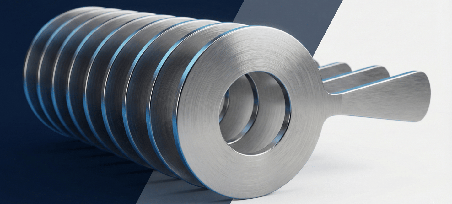
An orifice plate is a thin, flat metal plate with a precisely machined hole (orifice) in the center. It is a Primary Flow Element used to measure the flow rate of a fluid (liquid, gas, or steam) using the Differential Pressure (DP) method.
It operates on Bernoulli’s Principle, which states that as the velocity of a fluid increases, its pressure decreases. When fluid passes through the orifice, a pressure drop occurs. By measuring the difference in pressure between the upstream and downstream sides, the flow rate can be calculated with high precision.
Applications of Orifice Plates
Orifice plates are versatile and used across almost every heavy industry:
Oil & Gas: Measuring crude oil flow in pipelines or natural gas at wellheads.
Power Generation: Monitoring high-pressure steam flow in boiler circuits to ensure turbine efficiency.
Chemical Plants: Precise dosing of chemical volumes into a reactor where accuracy is vital for the reaction.
Water Treatment: Measuring the flow of treated water in large municipal distribution mains.
HVAC Systems: Balancing chilled water flow in large-scale industrial cooling systems.
Types of Orifice Plates
Choosing the right geometry is essential for measurement accuracy and preventing debris build-up:
Concentric Orifice Plate: The most common type. The hole is in the exact center. Used for clean liquids, gases, and steam.
Eccentric Orifice Plate: The hole is shifted towards the bottom (for gases with entrained liquids) or top (for liquids with entrained gases) to prevent pockets from building up.
Segmental Orifice Plate: Features a semi-circle hole. Ideal for slurries or dirty fluids where solids might otherwise clog a concentric plate.
Restriction Orifice (RO): Designed specifically to reduce pressure or limit flow rate rather than measure it.
Engineering Details & Sizing Criteria for Orifice Plates
Sizing an orifice plate isn't just about picking a hole size. It requires complex fluid dynamic calculations based on ISO 5167-2 or ISO 15377 standards. Key parameters include:
Beta Ratio (β): The ratio between the orifice bore (dd) and the pipe internal diameter (DD). Ideally, this should stay between 0.3 and 0.75 for maximum accuracy.
Reynolds Number (Re): Determines whether the flow is laminar or turbulent.
Discharge Coefficient (Cd): A factor that accounts for the energy loss due to turbulence.
Permanent Pressure Loss (PPL): The pressure that is never recovered after the orifice.
Plate Thickness: Must be sufficient to withstand the differential pressure without bending (buckling).
How to Size an Orifice Plate
Manual sizing involves iterative calculations. You start with a target Differential Pressure (DP), then calculate the required bore size, check the Reynolds number, and re-calculate the Discharge Coefficient until the numbers converge.
The traditional manual process:
Collect fluid properties (Density, Viscosity, Isentropic Exponent).
Define pipe material and internal diameter.
Determine the maximum and minimum flow rates.
Calculate the Beta Ratio and check against ISO 5167 limits.
Verify mechanical thickness and drain/vent hole requirements.
Simplify Your Workflow with the Juggernoax Sizing Tool
Engineering teams no longer need to rely on prone-to-error spreadsheets. Juggernoax has developed a professional, cloud-based Orifice Plate Sizing Tool that does the heavy lifting for you.
How to use our tool:
Input Fluid Data: Select your state (Liquid/Gas) and enter properties like Density and Viscosity.
Define Pipe & Flow: Enter your pipe ID and required flow rates.
Instant Results: The tool instantly calculates the Beta Ratio, Reynolds Number, and required Orifice Bore.
Download Datasheet: With one click, generate a professional .xlsx datasheet ready for your project submittal.
[Try the Sizing Tool Here: www.juggernoax.com/orifice-plate-sizing]
Frequently Asked Questions (FAQ)
Q1: What is the standard for orifice plate sizing?
A: The most globally recognized standard is ISO 5167 (Part 2). It defines the geometry and method of use for orifice plates installed in full-bore conduits.
Q2: What is a "good" Beta Ratio for an orifice plate?
A: For most industrial applications, a Beta Ratio (β) between 0.3 and 0.7 is recommended. A β below 0.3 can cause high pressure loss, while a β above 0.7 reduces the sensitivity and accuracy of the pressure reading.
Q3: Can I use an orifice plate for steam flow measurement?
A: Yes. Orifice plates are excellent for steam. However, ensure the material is compatible with high temperatures (usually 316 SS or higher) and that the sizing accounts for the Isentropic Exponent (κ).
Q4: What is the difference between a Flow Orifice and a Restriction Orifice?
A: A flow orifice is used to measure flow rate using a transmitter. A restriction orifice (RO) is used to intentionally drop pressure or limit the flow to a specific value.
Q5: Why is my calculated Beta Ratio out of range?
A: This usually happens if the pipe size is too small for the required flow rate or if the chosen differential pressure (DP) is too low. Adjusting the DP range can often bring the Beta Ratio back into the optimal range.
Technical Disclaimer & Limitation of Liability:
The Juggernoax Orifice Plate Sizing Tool is provided as a technical resource for preliminary engineering guidance and estimation purposes only. By using this tool, the customer agrees to the following:
Mandatory Re-verification: It is strictly advised that the customer re-verifies all generated data, calculations, and bores independently before proceeding with procurement, manufacturing, or installation.
No Liability: Juggernoax shall not be held liable for any direct, indirect, incidental, or consequential losses, damages, expenses, or process failures that may occur at the customer’s end resulting from the use of this tool.
Assumption of Risk: The user assumes all responsibility for ensuring the final design meets specific project safety and operational requirements.